Timelapse cameras are fun. I’ve done a few timelapse videos (like this one with a really crappy webcam driven by an original Eee PC laptop) and I have some ideas for other long term videos in the future, so I wanted a higher quality, more autonomous setup. My requirements:
- Waterproof so I can strap it to a tree for a few weeks
- Long battery life, so I can strap it to a tree for a few weeks
- Infinitely configurable delay between images depending on my goal for the video
- Easy to retrieve the images from it
- Don’t take pictures over night, because I’m lazy and don’t want to manually weed out black pictures. Sleeping over night means more battery life and less storage used too.
A Raspberry Pi seemed like a perfect platform. They are low power, they have camera module support, they’re small, and they’re cheap. With some extra hardware and scripting I can also turn it off between pictures to save even more power.
Here’s how I built it. Part 1 is the hardware setup and part 2 is the software.
Parts List
- Raspberry Pi A+. From my research at the time of build, this seemed to be the lowest power Pi with a camera port. $20 from Allied Electronics.
- Raspberry Pi PiNoIR Camera Module V2. The v2 is 8MP where the original was only 5MP. $25 from Allied Electronics. Note that the PiNoIR does not have an IR filter and is designed for use at night with IR illumination.
- A micro SD card for the Raspbian OS. I had an old 2GB sitting around, which is plenty for this project because I only need a minimal OS.
- A plastic, waterproof ammo case from Harbor Freight. $8
- A 32GB+ flash drive. Each image is on average 4MB, so 32GB will get you about 8000 images. Am image every 5 minutes for 8 hours a day = 96 images/day for 83 days before you have to empty it. I recommend to not get the cheapest one you can find. I did that with my first attempt and couldn’t get it to consistently mount on boot.
- A 12v battery. I had a spare UPS I wasn’t using anymore, so I salvaged the 8AH battery from that. Plus side is I use the UPS unit to recharge it.
- A MoPi. This is the power control brain, allowing timed power up at whatever interval I want to take the picture. I got the low profile version but looking back I wish I got the stackable version to make it easier to hook up the RTC.
- A DS1307 RTC breakout to keep time. This isn’t strictly required, but I wanted to time stamp the images that are taken and this is the only way to get somewhat accurate time on the Pi. It also lets us sleep over night.
- Some miscellaneous wire, two insulated crimp wire connectors for the battery, and a couple 12k resistors. Optionally, a small SPST switch.
The hardware build
The basic setup is: camera, flash drive, RTC, and MoPi all plug into the A+. The MoPi plugs into the battery. Here’s a rough schematic of the important bits:
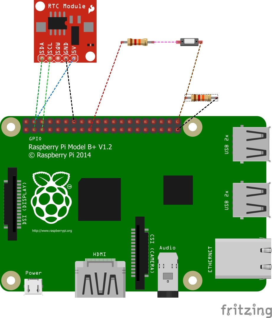
(Note – Fritzing didn’t have a diagram for the RPi A+, so I diagramed with the B+, which has equivalent GPIO).
The RTC is pretty straight forward – connected as required for I2C. Adafruit has a great setup tutorial.
The switch will be used to allow the Pi to boot without taking a picture. An autonomous build like this boot, a script runs to take a picture, then it shuts down again. But what if you need to do maintenance on the OS? You need to be able to break the shutdown cycle somehow. So the script checks the GPIO to bypass the script if you want to stay booted.
The resistor between ground and GPIO21 is a 12k pull down resistor. The switch is connected to 3.3v with a 12k resistor to limit current when the switch is on. When GPIO21 is at 0v (pulled down) operation is normal. When GPIO21 is at 3.3v with the switch on, the script will be bypassed and the OS will stay booted. Note that I’m not actually using a switch. I’m just using a simple jumper.
The MoPi is not pictured here, but it sits on top of the Pi, covering pins 1-26. One nifty feature of the MoPi is you can power the Pi from multiple sources. A future enhancement could be adding a second battery to make continuous operation possible while the main battery is being charged, or a solar panel to extend the life of the battery. Currently, the battery is connected to ground and input #1 on the MoPi.
The Pi camera is connected to the camera port. (imagine that!)
One challenge with the A+ is the one USB port. Luckily I had a USB NIC that also has a USB hub as part of it. After I got the OS set up, I plugged in my NIC and the flash drive into the HUB, then did the rest of the setup over SSH. Once I was ready to go, I disconnected the hub and plugged the flash drive directly into the one port.
Pictures of my setup
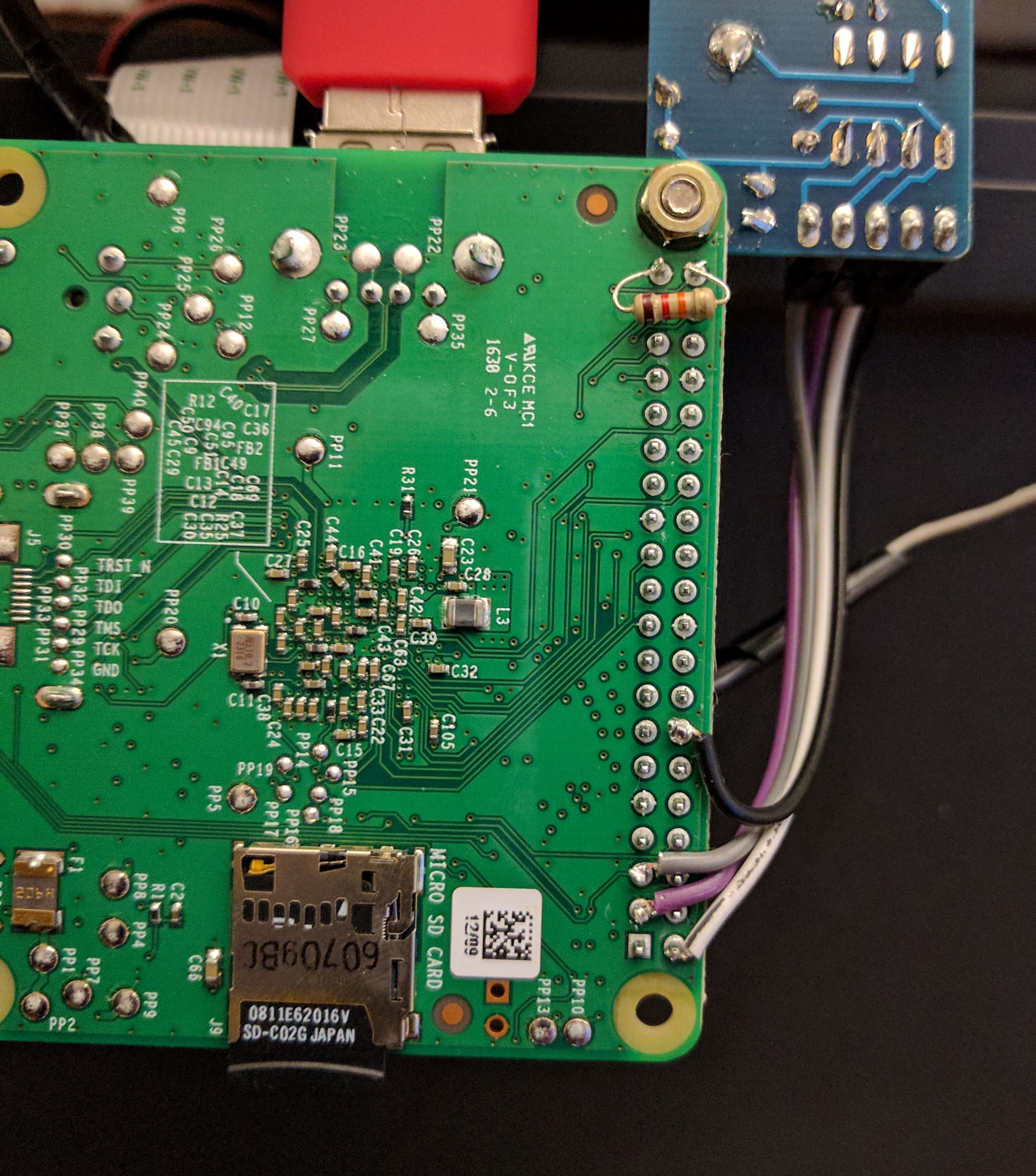
The back of the Pi. The resistor across the top two pins is the pulldown. The connections at the bottom are for the RTC. I soldered directly to the Pi as it is dedicated to this project. If I bought the stackable MoPi I might have used jumpers instead, but this is more permanent.
sdf
a href=”https://www.makethenmakeinstall.com/wp-content/uploads/2017/05/IMG_20170506_202143.jpg”>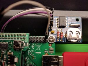
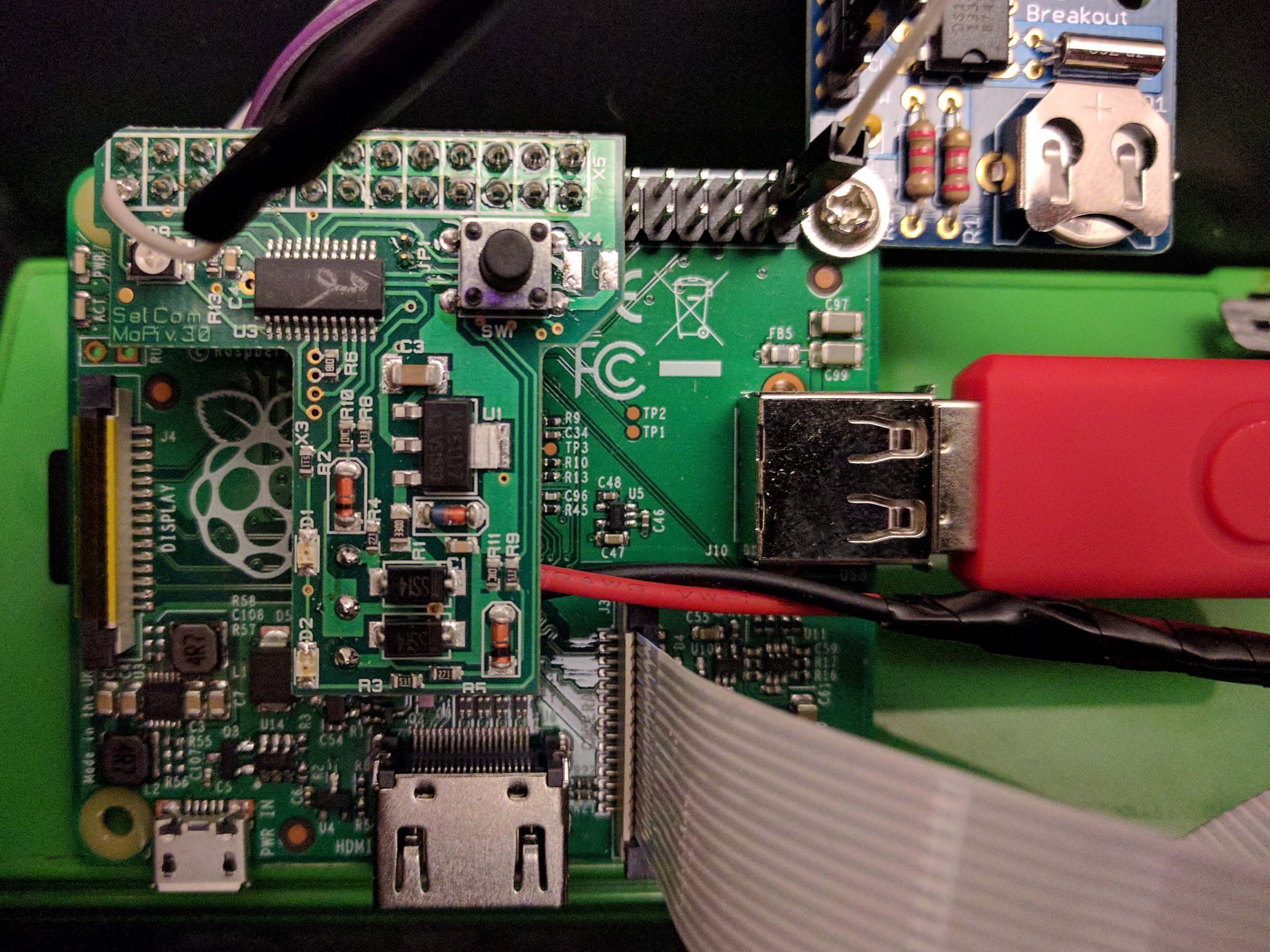
I mounted the RTC right to the Pi using a small screw and nut. You can also see the jumper connected to pin 40 – this is the bypass wire that will prevent the script from running when it connected (as it is in the picture).
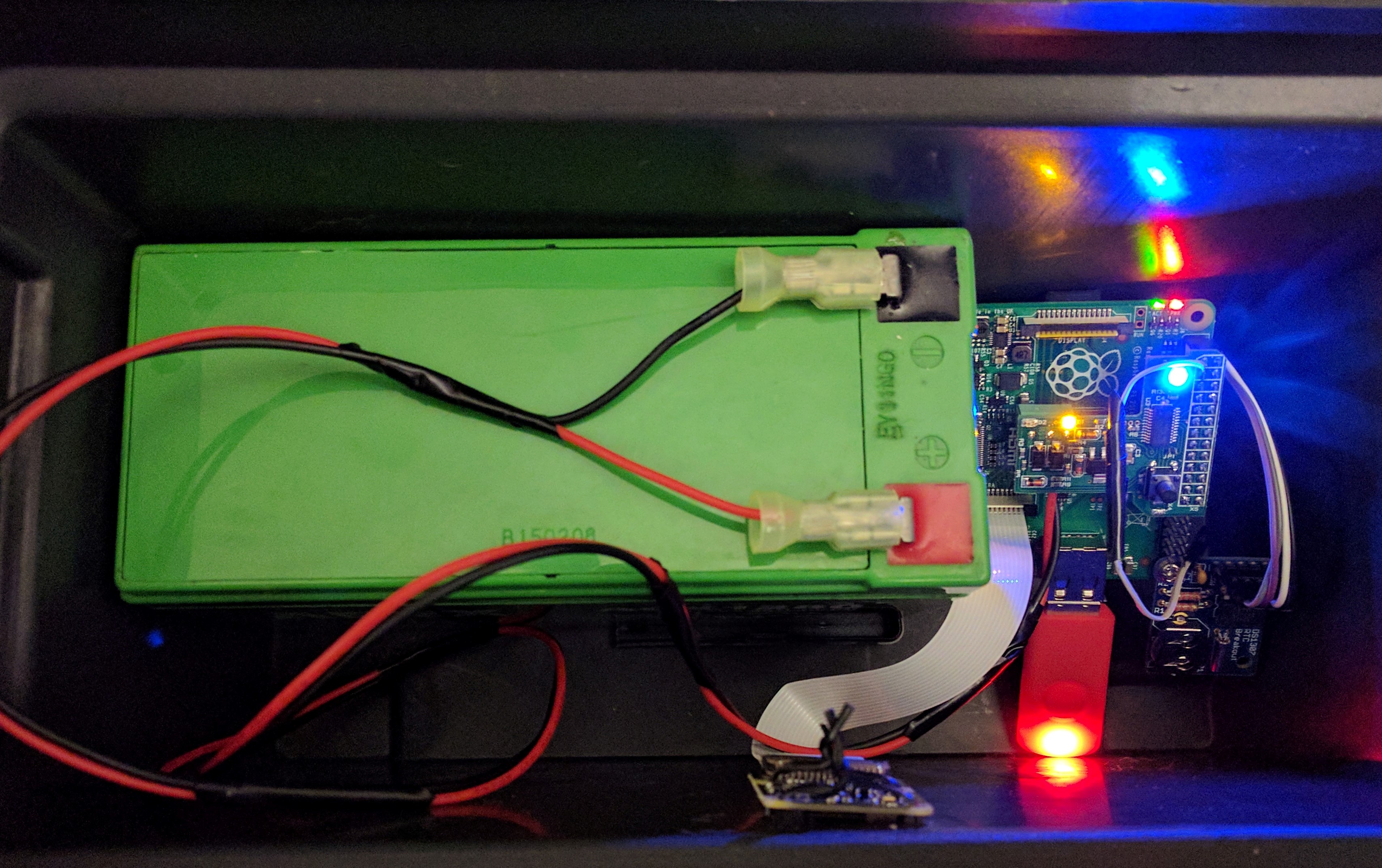
Everything in the ammo box.
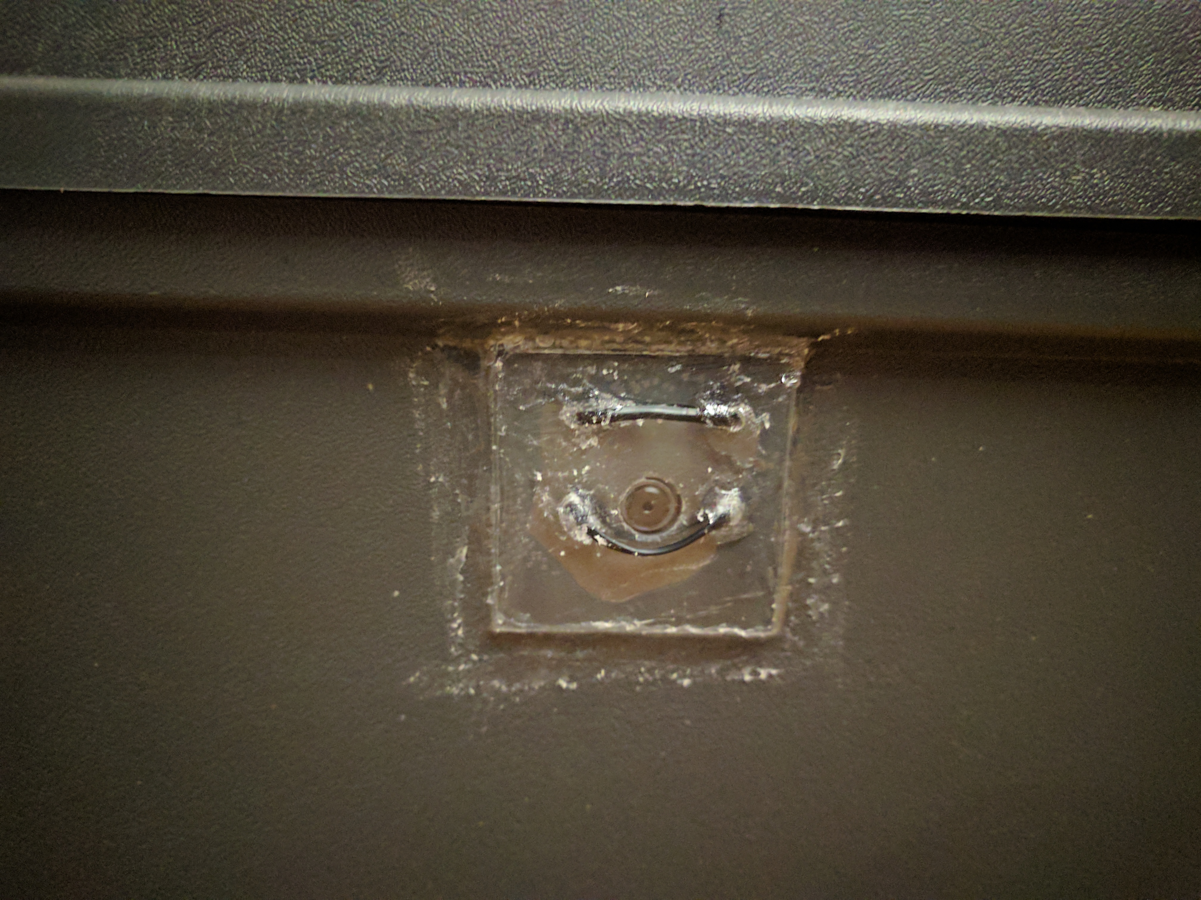
I drilled a small hole just large enough for the camera in the ammo box and covered it with a piece of plexiglass. I used twist ties to hold the camera in place. I had originally planned to use small screws and nuts to hold it with these twist ties as a temporary fix, but the ties work just fine. I used Household Goop to seal around the plexi and all holes so that water can’t get in.
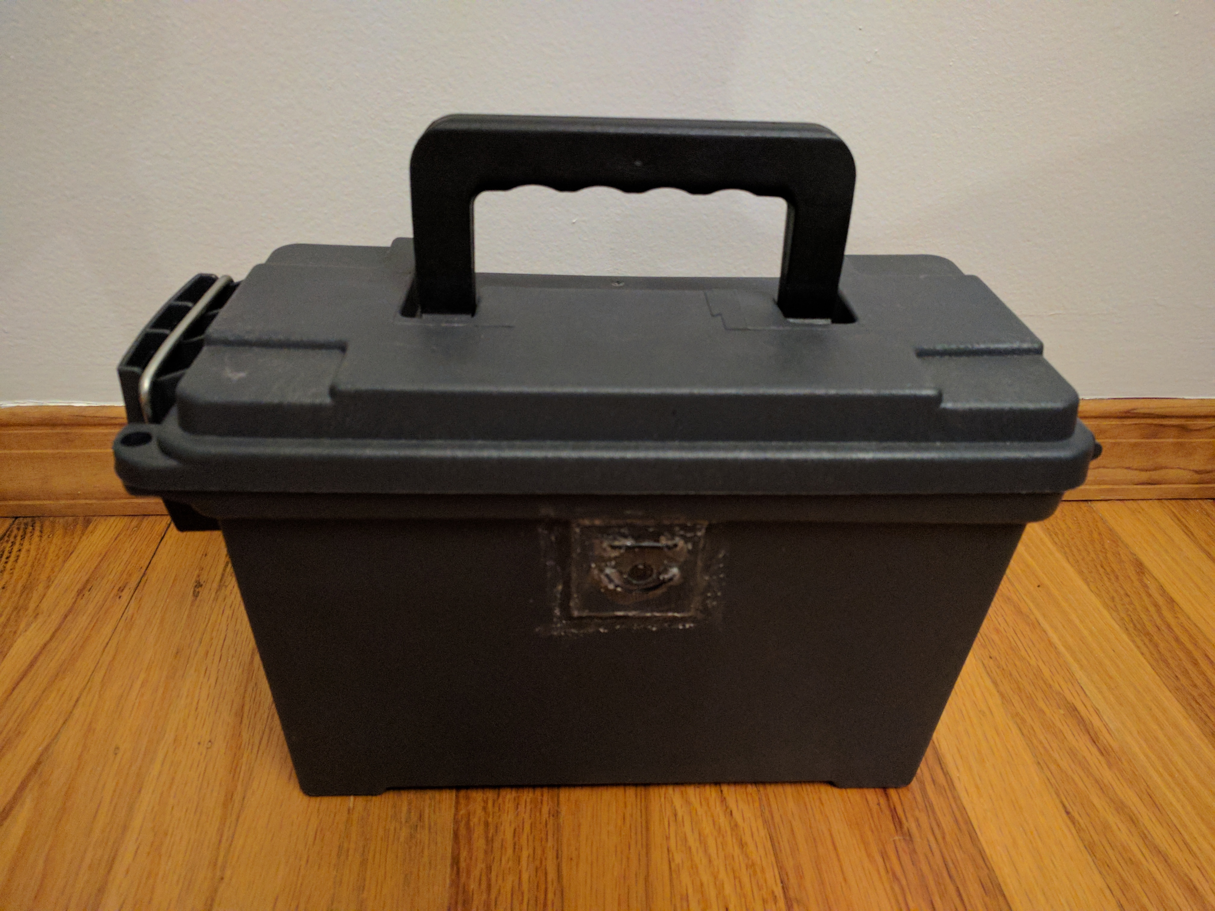
The finished, closed case, ready to be strapped to a tree.
That’s about it for the hardware. Part 2 has the OS and software setup that makes the magic happen.